
Air Impingement Ovens: How Air Fingers Direct Hot Jets
2026-11-09
Air Impingement Ovens: How Air Fingers Direct Hot Jets
Air Impingement Ovens direct heated air toward a product through arrays of small openings. A conveyor carries the product through the chamber, while a blower and air fingers shape the air delivery. The oven temperature, the location of the jets and the length of time spent in the chamber describe different parts of the process.
The blower and the air fingers have separate roles
Middleby Marshall's X70G/X55G manual identifies the main blowers as the components that move hot air from the burner to and through the air fingers. The air fingers then direct it through patterned nozzles inside the chamber. This description separates the heat source, the equipment that moves the air and the final arrangement that points the streams toward the product.
An airflow sketch can begin with a larger stream arriving at an air finger. Each opening then supplies a smaller jet. Instead of treating the entire chamber as having one air direction, the sketch shows multiple streams aimed from positions fixed relative to the belt. That is the specific arrangement described by air impingement.
Jet patterns can address the two sides of the conveyor
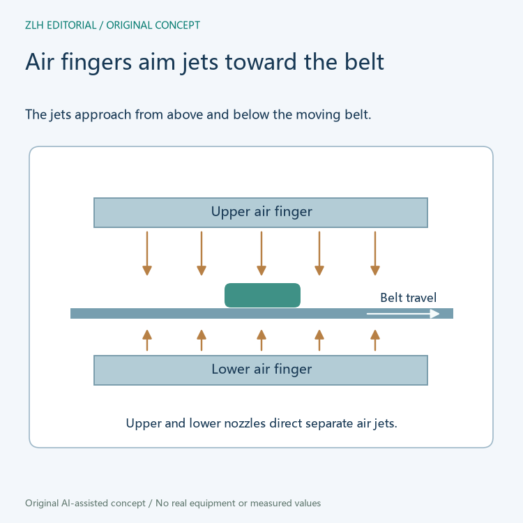
The Middleby manual locates patterned nozzles both above and below the conveyor. Downward and upward streams approach the product from opposite sides. A cross section can show their relation to the moving belt and the product without assigning the same flow pattern to every model.
Part of the usefulness of the word finger is that it identifies a distribution assembly rather than the individual hot stream. An air finger may have several openings along its length. A specification that mentions upper and lower fingers is describing where those assemblies are located. The jet locations are the points at which their directed air enters the chamber.
The jets change airflow at the product surface
Lincoln's Digital Countertop Impinger sheet describes hot air delivered under pressure in small jets around the product. Near a surface, the way moving air approaches and leaves affects the exchange of heat with that surface. Directing a stream onto the surface supplies a different local flow condition from letting warmed air move broadly through the chamber.
The chamber temperature still describes a thermal condition, but it does not show the direction or spatial pattern of the air. One chamber reading could accompany several nozzle arrangements. A useful equipment description therefore keeps the heating system and the air delivery system separately named.
Conveyor travel controls how long the product is exposed
The Lincoln sheet describes a variable-speed continuous conveyor. The conveyor moves a product from the entrance toward the exit, through the portion of its path exposed to the chamber airflow. For a fixed travel distance through that region, higher belt speed means less time in the region. Lower belt speed means more time.
In a conceptual time comparison, doubling speed halves the time over the same length. The nozzles remain in place while the product moves past them. Thus changing travel time is a different action from changing cavity temperature or repositioning a source of air. A record showing several products can identify the chamber length and belt travel separately from the air paths.

For example, two objects at different points on a wide belt may pass through the chamber for the same duration but meet different portions of a nozzle pattern. If both remain on the belt from entrance to exit, belt travel fixes the duration. Their lateral locations determine which jets lie above and below their paths. This is one reason a diagram can show both across-belt position and along-belt travel.
Equipment records can preserve all three conditions
A side section shows how jets approach the product. A plan view shows the belt direction and the sequence of jet regions along the path.
The two manufacturer references explain why temperature, air distribution and belt motion appear as different terms in an oven description. A drawing can identify which jets act near the product and how the belt crosses those regions. The product's own geometry and position affect which surfaces those jets reach.
If one comparison concerns how long a product spends in the chamber, the belt direction and speed are directly relevant. If it concerns air distribution, the appropriate view shows the nozzles above and below the belt. A cavity temperature value adds context to either comparison while answering its own question about the air being heated.
The Middleby Marshall X70G/X55G manual identifies blowers, conveyor and upper/lower air fingers. The Lincoln DCTI data sheet describes small hot-air jets and the variable-speed conveyor. See the food equipment section and the technical article directory.