
Rotor-Stator Mixing: Workhead Shear and Flow Paths
2026-11-07
Rotor-Stator Mixing: Workhead Shear and Flow Paths
Rotor-stator mixing concentrates part of a mixing process inside a workhead. A rotor moves inside a stationary member with openings, drawing material inward and moving it through a narrow region near the rotor tips. The material then leaves through the stator openings. How it travels after that depends on whether the head returns material to a vessel or sends it along a pipe.
The workhead draws material into a defined path
Silverson's batch mixer brochure describes a head positioned inside a vessel. The rotor draws material toward the center of the head and moves it outward toward the surrounding stator. In its illustrated batch example, material enters from below and leaves in a radial direction. The rest of the vessel supplies the material that the head draws in again.
The rotor and stator both affect this path. The rotor turns and transfers motion to the mixture. The stator stays in place and provides the opposing surface and the exit openings. These are separate working roles. A view of the vessel alone may show where the mixer sits without showing the internal route that the material follows.
The tip clearance and exit openings are different regions
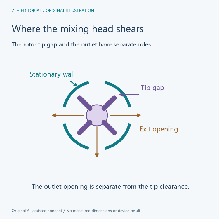
Near the edge of the rotor, the mixture passes through the small clearance between the moving blade tips and the stator wall. The difference between the moving surface and the stationary surface produces strong changes in the material's velocity across that region. The manufacturer's explanation associates the clearance with a milling or dispersing action.
The stator openings add another part of the flow path. Material leaves the workhead through them at speed, which the brochure describes as another source of hydraulic shear. The tip gap and the exit openings are two different dimensions. A description that lists an opening shape alone leaves out the clearance where the material first passes close to the blade tips.
The screen geometry belongs with the task
The batch brochure gives examples of interchangeable head and screen geometries. It associates an emulsor screen with liquid mixtures and describes slotted options for breaking up fibrous material. The relevant distinction is the route and action produced by a particular head. A broad machine label can cover more than one arrangement of openings.
In equipment records, dispersing a powder and reducing droplet size in a liquid mixture are different outcomes even if both make use of a high-shear head. The product being processed and the purpose of the pass through the head give meaning to the screen description. An equipment name by itself does not identify the material condition entering or leaving the head.
Batch circulation and inline transport send the outlet to different places
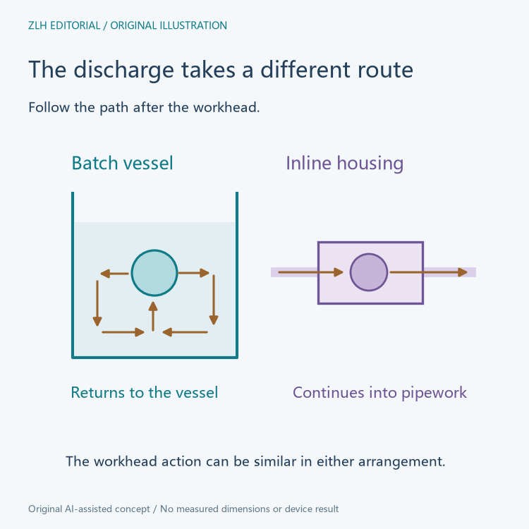
In the batch example, the flow expelled from the head returns to the main body of the vessel. Intake and discharge together establish a circulation pattern. Material already processed in the head can join other material in the vessel and encounter the head again. The vessel volume and the internal workhead are thus two parts of the same circulation route.
Silverson's inline mixing brochure section describes a related rotor and stator action inside a housing. After material passes through the stator openings, it continues through the housing outlet and along pipework. The process layout determines where the line goes next. It could carry material to another part of the line or form part of a return loop depending on the installation.
The same inline brochure lists both single-stage and multistage workhead configurations for one product series. The number of stages inside the housing describes what happens during a pass through the machine. The number of times a batch is sent through the housing describes something else. A circulation drawing is clearer when it shows the return route separately from any additional stage inside the head.
Describe the internal path and the plant path separately
A useful mixer record can identify the workhead, the screen or outlet openings, the inlet route and the destination of the discharge. This preserves the difference between the shear region inside the head and the larger movement of material around the process. It also helps a reader distinguish an in-vessel recirculating example from an inline head attached to a pipe.
The same distinctions help when comparing two drawings. A line around a batch vessel can show where the mixture travels, while a cutaway of the head explains where the material passes the moving tips. Both views are needed to connect the local mixing action with the overall flow.
For a kitchen or food preparation machine, the same vocabulary makes it easier to distinguish the work done near the rotor from the way the whole vessel or line moves material through it. Related material appears in the food equipment section and the technical article directory.