Scraped Surface Heat Exchange: Wall Film and Blade Roles
2026-11-07
Scraped Surface Heat Exchange: Wall Film and Blade Roles
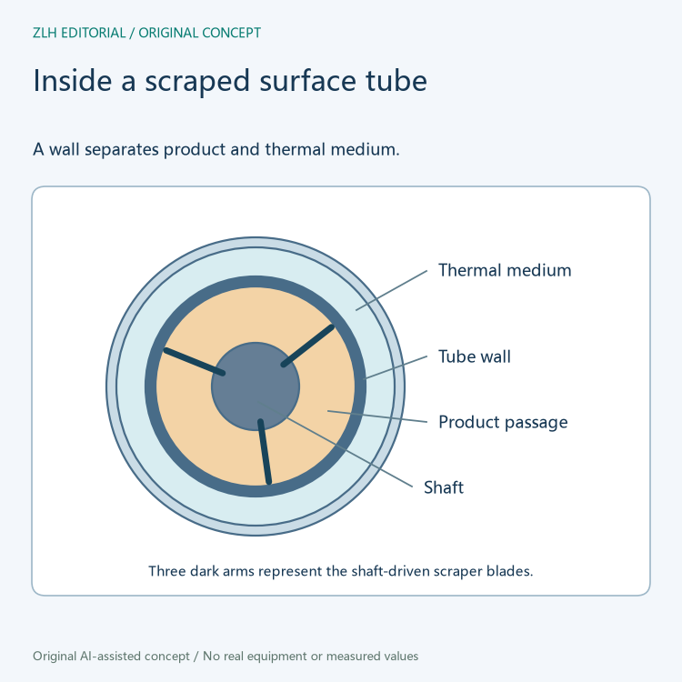
Scraped surface heat exchange adds a moving element directly inside the product channel. In the concentric design illustrated by SPX FLOW, a shaft runs along a heat transfer tube and carries blades that sweep the inner wall. Product travels in the gap around that shaft, while a heating or cooling medium flows in a jacket outside the tube. The blade action helps explain why this type of exchanger appears in food equipment literature for materials such as sauces, pastes and creams.
Three paths meet at the heat transfer tube
The product has an inlet and an outlet. Between them it occupies an annulus, the ring shaped space between the shaft and the inner surface of the tube. The heating or cooling medium has its own inlet and outlet on the jacket. The metal tube separates these streams and provides the solid path through which heat travels. In a heater the wall transfers energy from the medium toward the product. In a cooler heat crosses the same boundary in the other direction.
The motor adds a third path for energy. Its shaft delivers mechanical motion to the scraper blades. The blades travel circumferentially inside the product space as the bulk product moves along the tube. This distinction is useful on cutaway drawings. A curved arrow around the shaft typically represents rotation. A longitudinal arrow beside it can represent the passage of product, even though both arrows appear within the same cross section of equipment.
A blade changes which product is at the wall
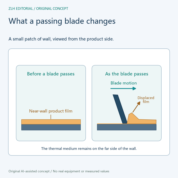
A viscous product can leave a comparatively slow moving layer next to the wall. That layer has to take up or release heat before energy reaches material farther into the channel. If the same layer stays there, its temperature can move toward that of the wall while the bulk remains farther from it. The literature calls this layer a product film. The word describes product at the interface, regardless of whether the material leaves a visible residue after processing.
As the blade passes, it moves the wall film into the surrounding product. Material from elsewhere in the channel then reaches the wall and starts exchanging heat there. The next blade pass repeats the process. SPX FLOW describes scraping and agitation together because the rotor can both renew the immediate interface and redistribute the removed film. Scraping happens at the boundary, while redistribution describes what happens to material within the larger flow space.
Flow direction is a separate design choice
Alfa Laval describes a vertical Contherm layout in which product enters near the bottom and moves up the cylinder. Its description includes a countercurrent arrangement for the heat transfer medium. In that arrangement, the two streams progress in opposite directions along the exchanger. Their temperature differences can therefore be distributed along the length of the tube instead of having the streams enter beside each other at one end.
Countercurrent describes how the streams run along the equipment. The rotor can still turn about the same axis as it scrapes. When reading a product drawing, follow the arrows for product and medium from their own labeled ports first, and then identify the rotor motion separately. The housing orientation and port configuration belong to the individual exchanger design.
Different geometries put the blades in different motion
The Votator II literature illustrates a concentric arrangement, an eccentric shaft arrangement and an oval tube. The first has the shaft centered in the heat transfer tube. An eccentric shaft changes the distance from that shaft to the wall around the tube, while an oval tube changes the wall geometry around the product space. These changes alter the way the scraper moves through the product. SPX FLOW presents them as designs for different product behavior rather than as different kinds of thermal medium.
In a machine description, the words blade, rotor and shaft often identify related parts. The shaft is the rotating support, and the blades are the surfaces that reach the heat transfer wall. The exchanger can also be described by the number or arrangement of cylinders. These details describe the geometry of the wall renewal system. They answer a different question from a heating medium connection or a thermal duty entry.
Read food equipment descriptions by function
For a cooking system drawing, locate the feed and discharge ports first. Next identify the jacket and the tube wall separating it from the product. Finally look for the drive and the elements that pass along the product side of that wall. This sequence reveals the three functions visible on the drawing: carrying the recipe stream, exchanging heat across a barrier and moving material away from the interface so the next portion can reach it.
The Alfa Laval Contherm technical page describes the vertical flow arrangement. The SPX FLOW Votator II brochure gives the concentric, eccentric and oval layouts in its Theory of Operation section on page four. Related entries are available in the equipment reference section and technical articles.