
Steam Trap Mechanisms: Disc Pressure and Float Buoyancy
2026-11-06
Steam Trap Mechanisms: Disc Pressure and Float Buoyancy
Steam Trap Mechanisms explain how a device can discharge condensate while retaining steam through a repeatable physical response. A traditional thermodynamic disc trap and a ball float trap do this in different ways. One uses flow and pressure acting on a disc; the other connects changing liquid level to the buoyancy of a float and the opening of a discharge valve.
A disc trap begins with an open discharge path
Spirax Sarco's official thermodynamic trap chapter describes the traditional disc type separately from impulse, labyrinth and fixed-orifice arrangements. The word thermodynamic therefore names a broader category than this single disc mechanism.
At startup, incoming pressure lifts the disc and allows cool condensate and air to leave through the discharge path. The same movable member later closes that path. The drawing is best understood by following the changing conditions above and below the disc, rather than treating it as a weight that simply falls shut whenever hot water arrives.
Flash steam changes the forces on the disc
As hot condensate passes through the inlet and experiences a pressure drop, part of it flashes into steam. The chapter describes the high-velocity flow beneath the disc creating a lower-pressure region that draws the disc toward its seat. At the same time, flash steam reaches the chamber above the disc and builds pressure there.
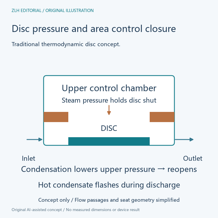
The upper chamber thus has a specific control role. It is not merely unused space inside a cover. Pressure in that chamber acts on the upper disc area, while the pressure distribution below depends on the inlet, flowing passage and discharge geometry. The movement follows the resulting force relationship across those surfaces.
The closed state depends on pressure and area
Spirax Sarco explains that the pressure above and below the seated disc can equalize while the trap stays closed. The effective area exposed above the disc is larger than the relevant area on the inlet side below it. Equal pressure values therefore do not imply equal opposing forces in this geometry.
Steam trapped in the upper chamber subsequently loses heat and condenses. As its pressure falls, the inlet force can lift the disc again and another discharge occurs. Condensation in the control chamber is consequently part of the reopening mechanism, not simply the condensate stream that the device is intended to remove from the steam system.
A ball float responds to the condensate level
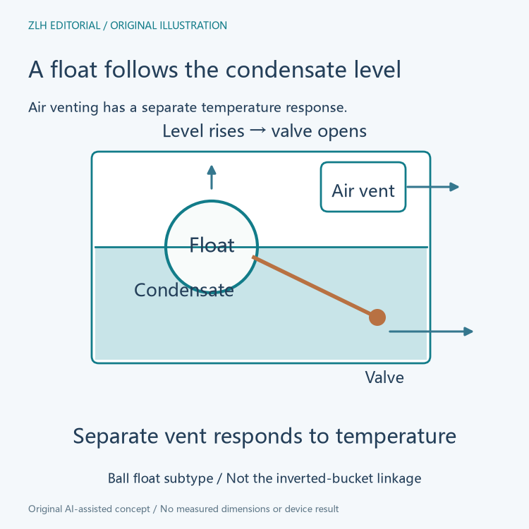
The official mechanical trap chapter describes a ball floating in condensate and linked to a valve. Incoming condensate raises the liquid level, which raises the float and opens the discharge valve. Falling level reduces the opening as the float descends.
This is a liquid-level response rather than the disc's upper-chamber pressure cycle. The outlet valve remains submerged in the chapter's float-trap explanation, supporting the separation between condensate discharge and steam retention. Within its applicable working conditions, a float trap can discharge condensate continuously as it arrives instead of waiting for the traditional disc's repeated closed and open states.
The air vent has a separate sensing role
A submerged discharge valve also prevents air from escaping through that liquid-controlled route. The chapter therefore describes a separate thermostatic air vent in the float-trap assembly. That vent responds to temperature conditions and provides an air escape path independently of the float's level response.
Calling the entire assembly a float trap should not erase this second mechanism. The float, its linkage and the condensate valve explain liquid-level control; the thermostatic element explains the separate air-venting function. The presence of a temperature-responsive vent does not turn float buoyancy itself into a temperature measurement.
Another mechanical subtype moves differently
The same mechanical chapter also explains the inverted bucket trap. Steam entering its bucket creates buoyancy that raises the bucket and closes the valve through the linkage. That account differs from the ball float, where rising condensate lifts the float to open its valve.
The category name mechanical is therefore insufficient to predict whether an upward-moving member opens or closes the outlet. Identifying the moving member, what gives it buoyancy and how the linkage acts on the valve preserves the distinction between the two subtypes.
Read the moving member together with its control medium
A useful component record names the traditional disc and its upper pressure chamber, or the ball float and its liquid-level linkage, before describing the discharge pattern. It can then identify a separate air vent where the cited float arrangement includes one. These relationships explain why similar external housings can contain different operating principles.
Both complete official chapters were read on November 6, 2026. The original diagrams show the control relationships without supplying installation dimensions or a maintenance sequence. Related background appears in the thermal equipment category and technical reference directory. Disc pressure forces and float buoyancy provide two concrete explanations for condensate discharge.