Progressing Cavity Pumps: A Helical Rotor and Stator
2026-11-06
Progressing Cavity Pumps: A Helical Rotor and Stator
Progressing Cavity Pumps move fluid through cavities formed between a helical rotor and a matching helical stator. The rotor turns inside the stator, and the cavities progress along the pump axis from intake toward discharge. The paired shapes create the transport mechanism; the visible rotation of a shaft is only one part of that relationship.
The rotor and stator form a working pair
PCM's official Moineau technology explanation identifies a helical rotor turning inside a helical stator. In the arrangement it describes, a precision-machined stainless-steel rotor works with a stator moulded from resilient elastomer. Their internal relationship establishes the cavities through which the product travels.
This makes the stator more than an outer cover. Its internal helical shape is part of the pumping geometry. Likewise, the rotor is more than a drive shaft carrying rotation into the assembly. Reading both shapes together explains why the pump contains an extended working region instead of a single open mixing chamber.
The cavities progress along the axis
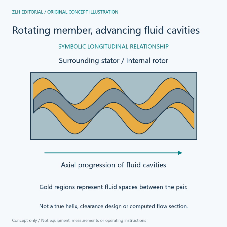
PCM describes a double chain of sealed cavities formed when the rotor sits inside the stator. As the rotor turns, the cavity pattern moves spirally along the pump axis. The source uses this progression to explain transport from the intake to the discharge while describing the cavities as retaining their shape and volume in the operating principle.
The axial progression is the useful distinction in a mechanism drawing. A rotating member and an advancing fluid region need different arrows because they describe different motion. Showing only a circular arrow at the drive would identify rotation but omit how the fluid is transferred along the working pair.
Positive displacement refers to the transport arrangement
The paired rotor and stator organize fluid into enclosed working cavities. That is the geometric basis for the positive displacement description in PCM's pump materials. It concerns how fluid is captured and moved through the pumping element, rather than simply naming the type of motor that drives it.
PCM also lists a relationship between flow rate and running speed among the technology's characteristics. The geometric explanation makes that relationship intelligible: repeated rotor motion repeatedly advances the working cavities. A numerical flow statement still belongs with the particular pump and configuration, rather than being supplied by the words positive displacement alone.
A stationary stator still needs resilient material
The word stator identifies its stationary role relative to the rotating member. It does not mean that the material can be described without its mechanical properties. PCM explicitly identifies resilient elastomer in the stator and separately explains why elastomers must withstand pumping action as well as the fluid being handled.
Its official in-house elastomer explanation treats these material demands as central to the pump. The working component therefore needs two descriptions: its helical geometry explains its relationship with the rotor, while its formulation and behaviour explain the material involved in that relationship.
Mechanical behaviour and fluid compatibility answer different questions
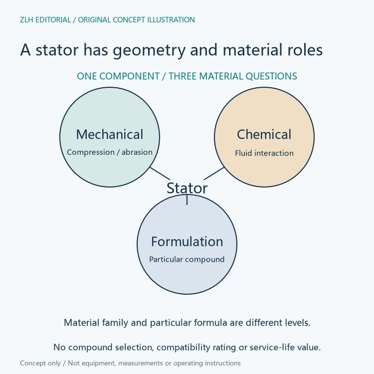
PCM lists mechanical tests involving static and dynamic behaviour, compression and bonding. It separately lists tribology topics such as abrasion and friction, together with chemical testing that includes swelling and changes in volume and hardness. These categories describe different ways in which an elastomer can be assessed.
That separation is useful when interpreting a material summary. A mechanical property does not by itself identify compatibility with an unspecified pumped fluid. Equally, a general chemical-family name does not supply the complete mechanical behaviour of the actual stator. The manufacturer's formulation and application context remain part of the component description.
Material names stay attached to their formulations
The elastomer page provides several formula identifiers within some material families. This is a concrete reminder that the family label and a particular compound are different levels of information. PCM connects its formulation work with laboratory assessment, mixing, injection and checks of the resulting parts.
For example, the page lists multiple PCM formula numbers under the nitrile family instead of presenting that family as one interchangeable material. Its testing categories also cover both changes in the material and interaction at the contacting surfaces. The physical component record can retain these distinctions without importing a separate application's material claim.
For an equipment explanation, the appropriate connection is between the actual stator material and the fluid and mechanical demands documented for it. The page's range of formulations supports that distinction without turning a general mechanism article into a universal compatibility table or a promise about a particular product's condition.
Further reading appears in the industrial mechanism section and equipment article directory. The helical pair explains how cavities carry fluid along the axis; the material record explains which resilient component participates. Keeping those linked roles visible gives a more complete account of a progressing cavity pump.